V400c Supplemental information on cable connections
Follow the instructions below
if required.
Connecting the
all-in-one cable if it is not already connected to the terminal
Connecting
Ethernet and power cables to the terminal without using the all-in-one
cable
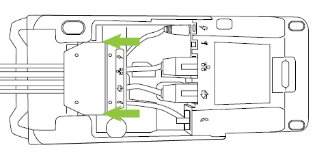
Connect
the all-in-one cable to the terminal
In the event that you need to
disconnect and reconnect the all-in-one cable, follow the instructions
below to complete that connection.
Turn
the terminal over so that you are looking at the underside
of the terminal. Lift the flap covering the connection well and remove
it to expose the connection well. |
|
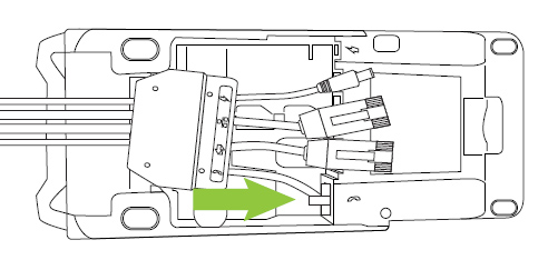
Plug the dial connection from the splitter into the
dial port.
Note:
Even though the dial and RS232 connections are not
used, plug them in anyway to ensure the splitter sits in the connection
well properly. If you leave them unplugged, you will not be able
to close the lid on the connection well. |
|
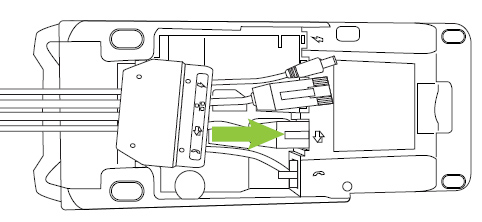
Plug the RS232 connection from the splitter into the
RS232 port. |
|
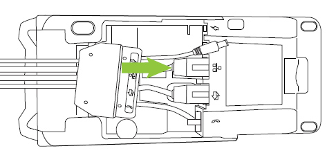
Plug the Ethernet connection from the splitter into
the Ethernet port
labelled with the network symbol ( ). ). |
|
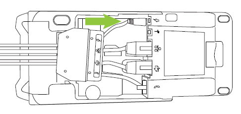
Plug the power connection from the splitter into the
power port labelled with the power symbol ( )
. )
. |
|
At the top of the connection well, slide the splitter
wedge over the splitter clips to secure the splitter in place
(it should be tight against the underside of the terminal).
|
|
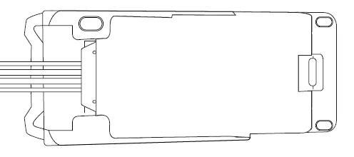
Close the flap to cover the connection well.
|
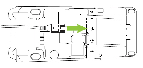
Connecting
cables to the terminal without using the all-in-one cable
In the event that you need to connect cables to the terminal and you
do not want to utilize the all-in-one cable, follow these instructions
to connect cables to the terminal directly.
Note: You
will use this method if you are connecting
the optional
external P400 PIN pad.
Turn the terminal over so that you are looking at the
underside of the terminal. Lift the flap covering the connection well and remove
it to expose the connection well. |
|
Plug the Ethernet cable into the Ethernet port labelled
with the network symbol ().
|
|
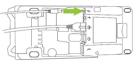
Plug the power cable into the power port labelled with
the power symbol . |
Replace the flap to cover the connection well. |