Follow the steps below to connect the cables to the VX 520 terminal and the Magic Box on the all-in-one connection cable.
Follow the instructions below to connect the all-in-one connection cable to the VX 520 terminal.
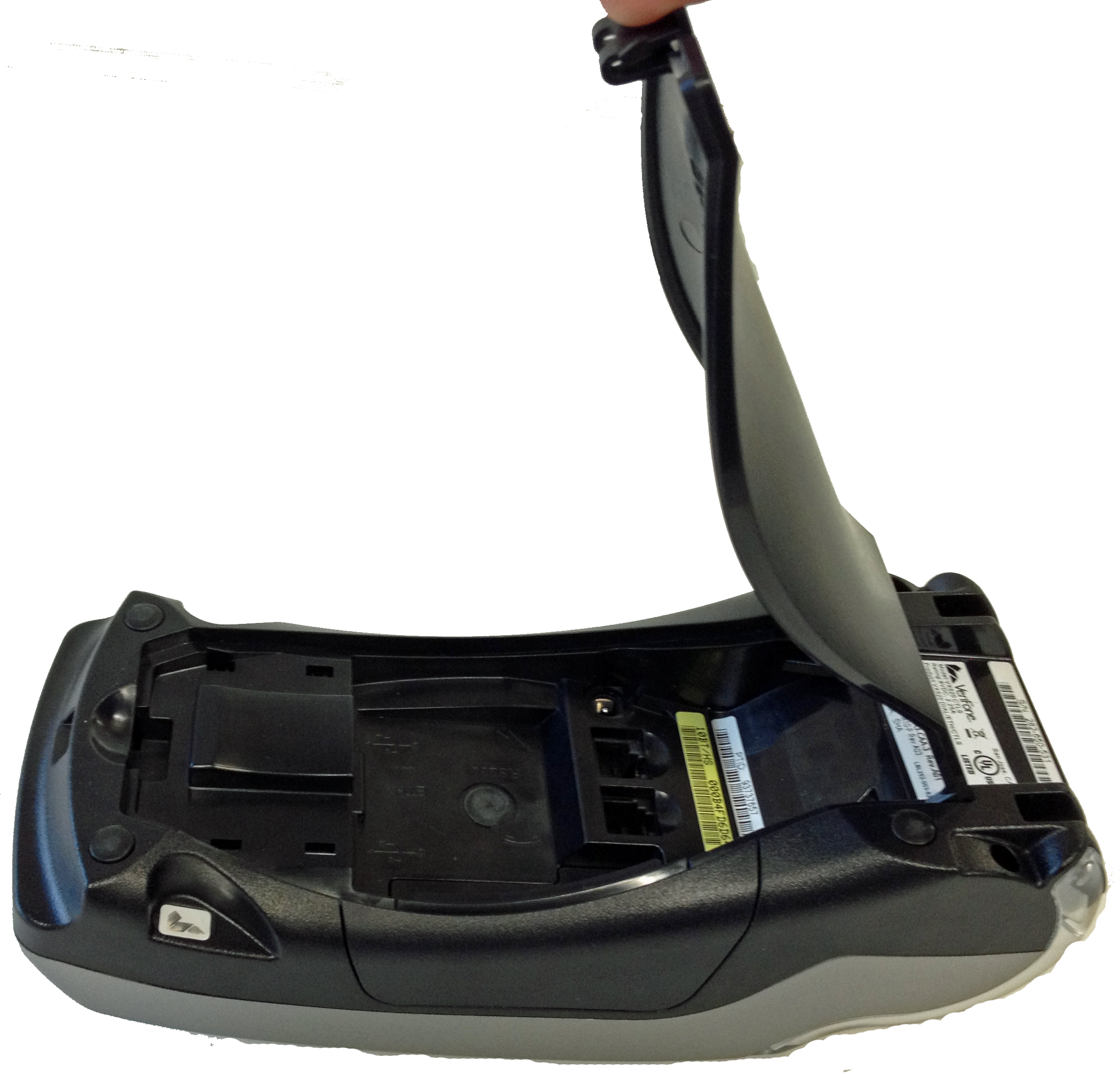
1. Turn the terminal over so that the underside is exposed.
2. Remove the cover on the connection well.
a. Lift the latch at the bottom of the terminal.
b. Flip
the lid up towards the top of the terminal.
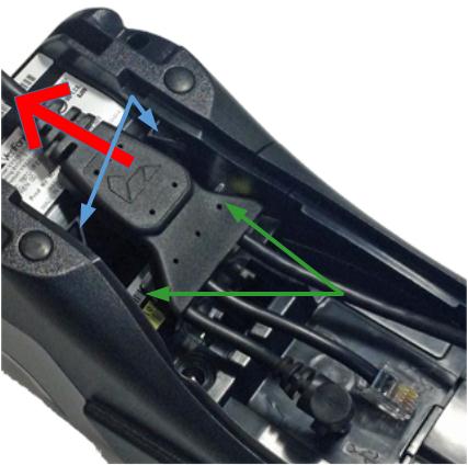
3. Once
the connection well is exposed, take the Splitter
and slide it underneath the clips near the top of the terminal (pull towards
the top of the terminal; shown with the red arrow in the image below),
so that the wings on the Splitter slide under the clips inside the connection
well. The blue arrows in the image below show the terminal clips; the
green arrows point to the wings.
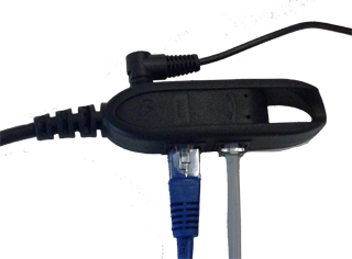
4. Once
the wings on the Splitter are secured under the clips, take the Ethernet
cable (the longest cable on the Splitter) and connect it to the Ethernet
port (labelled with the ETH
symbol).
5. Connect
the Dial cable (the medium sized cable on the Splitter) and connect it
to the dial port labelled with the ![]() symbol.
symbol.
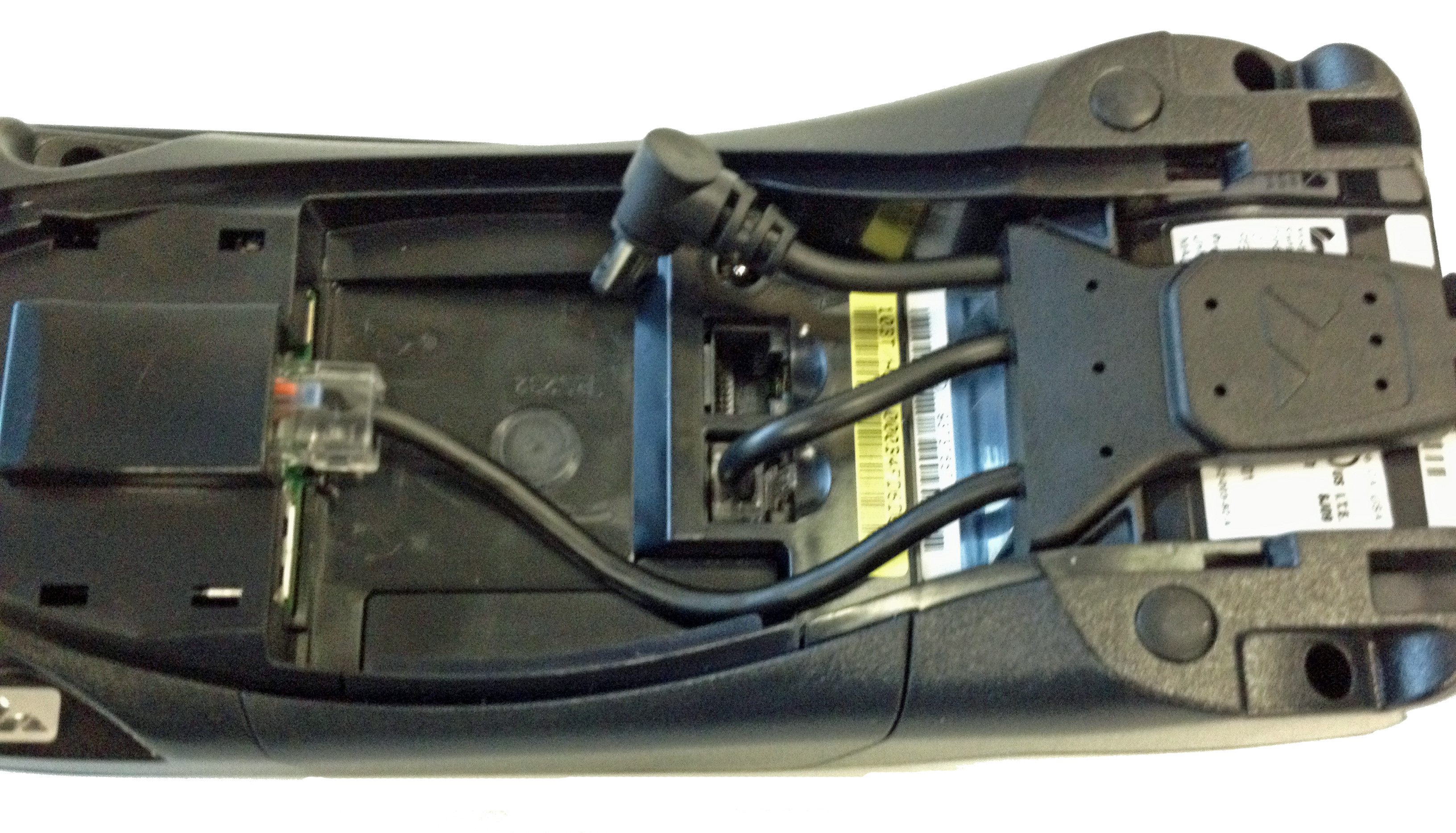
6. Connect
the power cable (the shortest cable on the Splitter with the silver and
black barrel connector) and connect it to the power port labelled with
the ![]() symbol.
symbol. 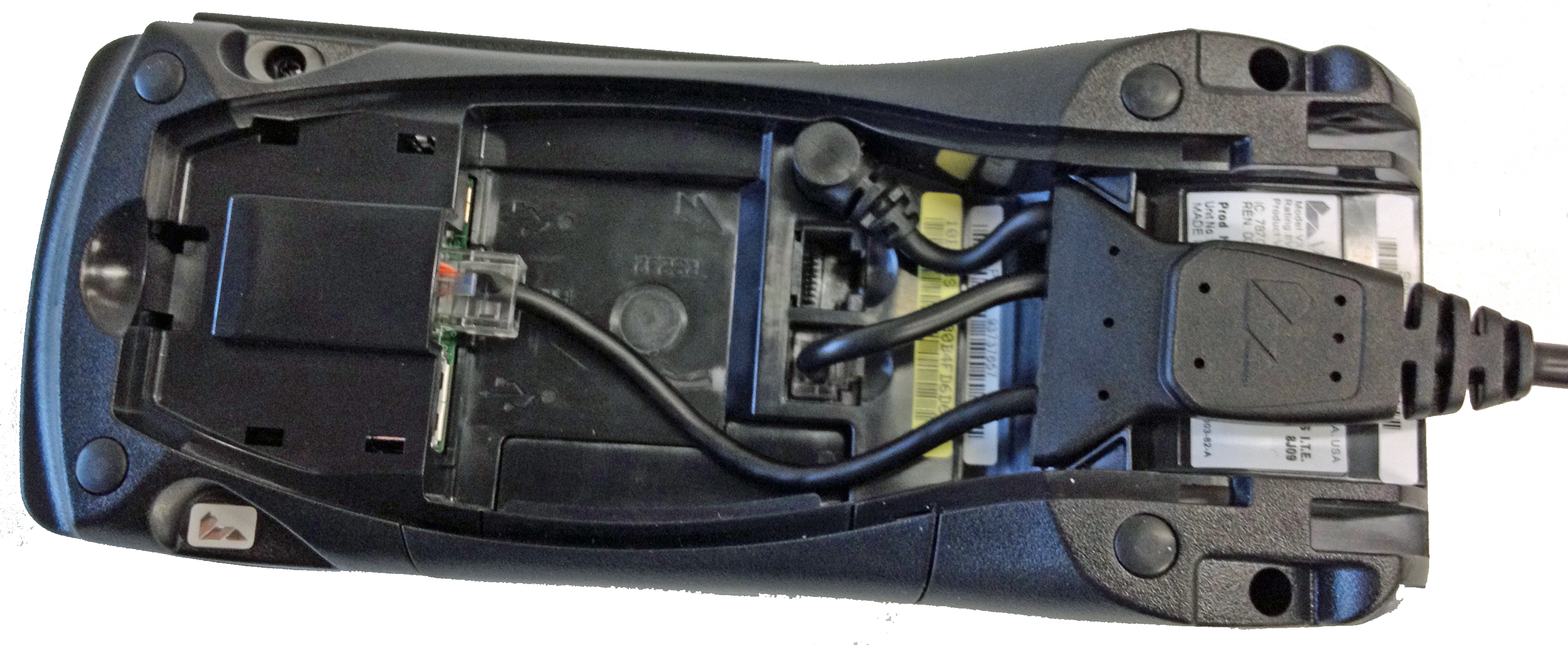
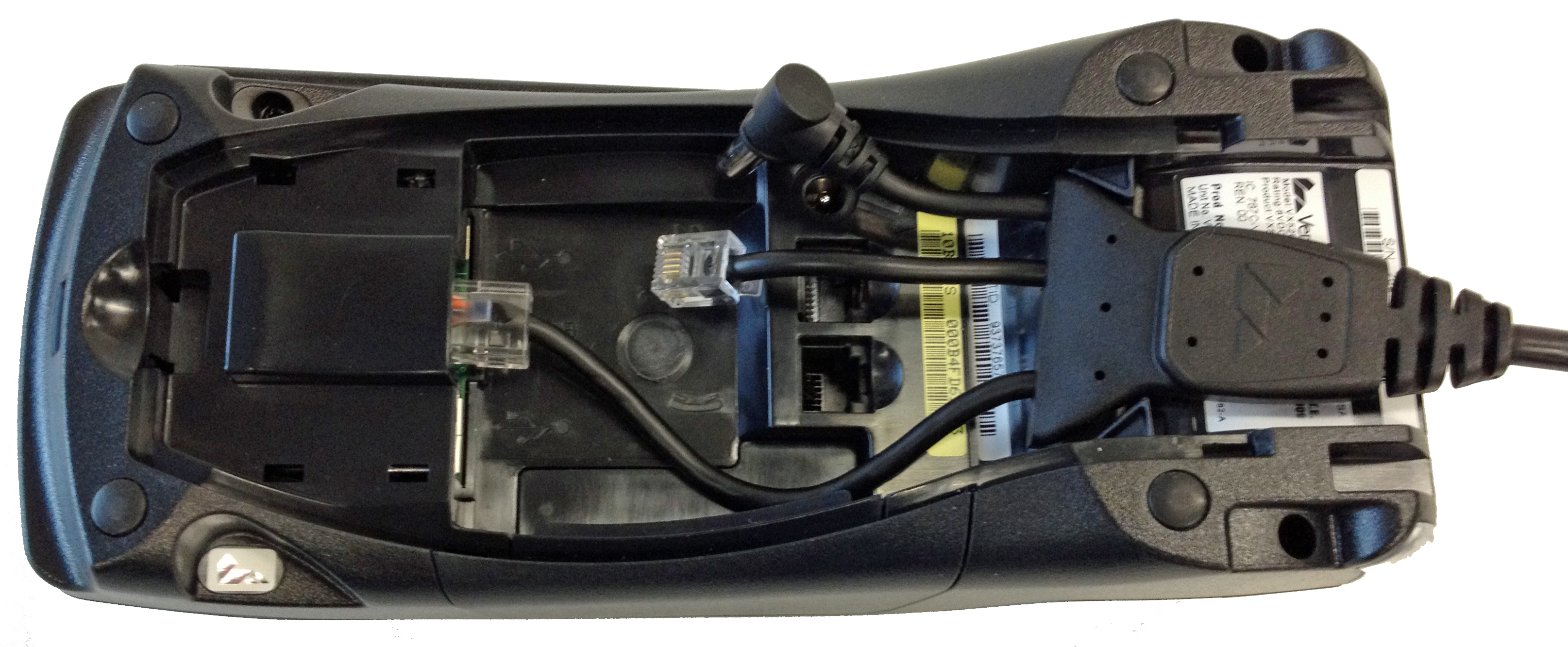
7. Ensure that the Splitter wings are secured under the clips and that it is positioned firmly.
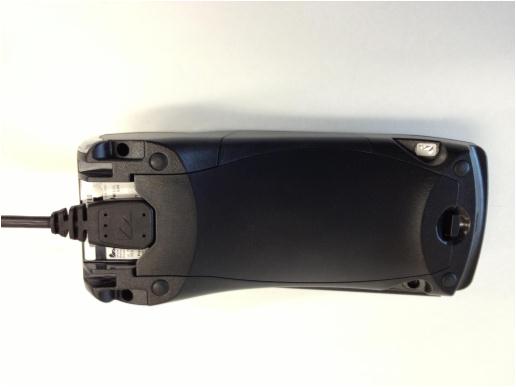
8. Take
the cover and swing it back over the connection well, snapping the latch
at the bottom into place.
Follow the instructions below to connect communication and power cables to the Magic Box on the all-in-one connection cable.
1. Connect an RJ 45 Ethernet Communications cable to the Ethernet port (labelled ETH) on the Magic Box.
2. Connect an RJ 11 Dial Communications cable
to the dial port (labelled with the ![]() symbol)
on the Magic Box.
symbol)
on the Magic Box.
3. Connect the power cable to the power port
labelled with the ![]() symbol.
symbol.